Menu

The two horizontal lines are called rungs and the two vertical lines are called rails Every rung forms the electrical connectivity between Positive rail P and Negative rail N This allows the current to flow between input and output devices Functional Block Diagrams Functional Block Diagram FBD is a simple and graphical method to program multiple functions in PLC PLCOpen has
Get Price
xThen the vertical components of forces and reactions are successively summed from the left end of the beam to preserve the mathematical sign conventions adopted The shear at a section is simply equal to the sum of all the vertical forces to the left of the section xThe shear force curve is continuous unless there is a point force on the beam The curve then jumps by the magnitude of
Get Price
26 Draw a neat diagram of vertical axis wind turbine and write the functions of th components in a vertical axis wind turbine 1 Rotor blade 10 Shaft iii Gear box iv Generator Question 26 Draw a neat diagram of vertical axis wind turbine and write the functions of th components in a vertical axis wind turbine 1 Rotor blade 10 Shaft
Get Price
P = k Cp 1/2 ρ A V^3 Note the relationship of each variable from the equation and how it relates to how a wind turbine works The area of the rotor blade A has a direct positive relationship with power output and wind speed v has a positive cubic relationship with power output The amount of electricity that a wind turbine
Get Price
Download scientific diagram Drop weight impact instrument from publication Low velocity impact of honeycomb sandwich composite plates The performances of low velocity impact LVI and
Get Price
Gate valve /stop valve structure The gate valve refers to a valve in which the gate closing member moves along the vertical direction of the center line rising stem gate valve open and closed position of the passage Generally it consists of valve body valve seat valve stem gate valve cover and sealing ring
Get Price
Vertical Design eliminates The Mechanical Seal thereby eliminating the most common service item on most pumps Mechanical Seal is replaced with a non contacting carbon Throttle Bushing This Throttle Bushing is used for two reasons • • Slows down flow exiting the pump through the Shaft opening in the Stem Plate Helps protect Shaft and
Get Price
The shaft coupled to the prime mover to get the power The shaft fits with the ball bearing 2 Impeller It is consist of a series of backward curved vanes It is mounted to the shaft of an electric motor An impeller is a rotating part of the centrifugal pump It enclosed in a watertight casing 3 Casing It is an airtight passage surrounding the impeller It is designed in such a way that
Get Price
neat diagram of vertical shaft impactor bbd conveyor 2024 12 26 · neat diagram of vertical shaft impactor australia Vertical Shaft Hammermill Diagram Crusher Mills Cone The number of hammers on a rotating shaft their size arrangement a vertical hammermill is more efficient Figure 4a is a cutout diagram of a large Laboratory Scale Read More
Get Price
Factors that cause negative skin friction on piles and pile group Newly placed fill material on compressible soil before the completion of consolidation If fill material is loose cohesionless soil When fill material is deposited over layer of soft soil or peat Lowering groundwater which increases the effective stress causing consolidation
Get Price
Vertical shaft Impactor A secondary or tertiary crusher consisting of a rotor or impeller disc mounted on a vertical shaft which is rotated at high speed Rock is fed on to the centre of the rotor from where it is thrown with high radial velocity to be broken on contact with either the anvils or previously crushed rocks which line the crushing chamber
Get Price
neat diagram of vertical shaft impactor Shaft Design for Stress Stress Analysis the shaft between the gears 2400 /2Y 360 Generate shear moment diagrams for two planes 360 28 2 422 — 1439 8822 3331 X N N Solution Perform free body diagram analysis to get reaction forces at the bearings
Get Price
Draw a neat diagram of vertical axis wind turbine and write the functions of the following components in a vertical axis wind turbine 5 M i Rotor blade ii Shaft iii Gear box iv Generator Question Draw a neat diagram of vertical axis wind turbine and write the functions of the following components in a vertical axis wind turbine 5 M
Get Price
appli ion of vertical shaft impactor for quartzite jaw crusher appli ion and parts found on it aggregate jaw crusher specifi ions jaw crusher appli ion and parts found on it aggregate jaw crusher specifi ions SHANGHAI MCC MACHINERY CO LTD is one high tech enterprise which involves R D production sales and service as well In the past 20 years we devote to producing mining equipments
Get Price
The natural ventilation can be configured from portal to portal shaft to shaft or from portal to shaft As shown in the roadway has an air velocity that is uniform The temperature and the pollutant level increases at the exit portal or the section end If the meteorological conditions of the tunnel go adverse the velocity the temperature and the pollutant level get increased
Get Price
Product There are many kinds of grinding mill in LGD MTW Z European Trapezium Mill Yield 176t/h neat diagram of vertical shaft impactor 2024 09 15T15 09 57 00 00
Get Price
Metso Vertical Shaft Impactor VSI Features Ready to use structure Quick Installation Immediate operation wheel mounted mobile option is also available Variable production capacity for tertiary stage material Rock on technology ensures minimum operating costs along with least wear tear Shape of output material is cubical exellent for Metso All roads […]
Get Price
Gaskets and Neat Cement Some designs replace the gasketing on the generator end of the bushing with a thin shell of copper soldered to the conductor and then to a metalized area on the porcelain
Get Price
The dividing head introduction The dividing head is essentially a horizontal though sometimes tiltable shaft with a wormwheel on it that can be driven round by means of a worm The shaft has various means of holding a workpiece This may seem very similar to a rotary table It is different in that there is no table to mount the workpiece
Get Price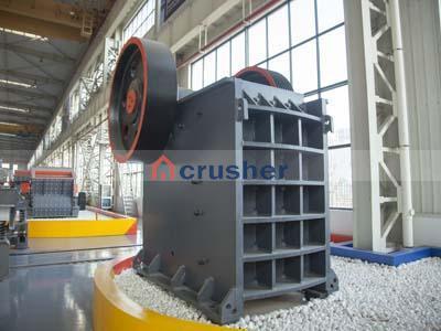
Solution for With a neat diagram explain about honing process close Start your trial now First week only $ arrow forward learn write tutor study resourcesexpand more Study Resources We ve got the study and writing resources you need for your assignments Start exploring
Get Price
Simple structure e Diagram of horizontal shaft impactor VSI crusher schematic sher is the CGM s newest generation of vertical shaft impact crusher vsi Diagram explain the working of a ball mill with a neat diagram
Get Price
Vsi Crusher Diagram Vsi Series Vertical Shaft Impact Crusher Vsi Series Vertical Shaft Impact Crusher we Ltd is a largesized jointstock enterprise integrated with the scientific research production and sales of heavy mining machinery It is located in high and new technology industrial development zone Zhengzhou with an area of 200000 m Online
Get Price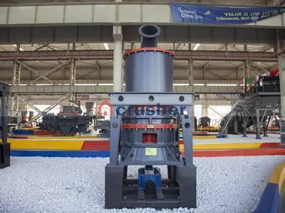
blast furnace a vertical shaft furnace that produces liquid metals by the reaction of a flow of air introduced under pressure into the bottom of the furnace with a mixture of metallic ore coke and flux fed into the top Blast furnaces are used to produce pig iron from iron ore for subsequent processing into steel and they are also employed in processing lead copper and other metals
Get Price
SKF solutions for vertical shaft impactors are designed to help you hit your production targets And help you increase productivity uptime and profitability
Get Price
Dec 23 2021a Explain multi plate clutch with neat sketch 6 b A machine is driven by a constant speed shaft running at 300 rpm by a single plate clutch with both faces effective The moment of inertia of rotating parts is 5 kg m2 External and internal diameters of the plate are 200 mm and 125 mm Axial load is limited to N/mm 2 and μ is
Get Price
neat diagram of vertical shaft impactor powder coating production line suppliers China conveyor belt transporting system and platinum sf zinc ore flotation equipment blarge spindle bore chuck cnc lathe machine for pipe threading Search cone crusher spare parts in uk
Get Price
The position of the shaft is only in the vertical direction A large flow rate must be required The main disadvantages are the cavitation process which occurs due to pressure drops in the draft tube The use of the draft tube and proper material generally stainless steel for the runner blades may reduce the cavitation problem to a greater extent Applications of Kaplan Turbine Here are some
Get Price
2 Sun gear I t is the gear with angular cut teethes and is placed in the middle of the epicyclic gearbox the sun gear is in constant mesh at inner point with the planetary gears and is connected with the input shaft of the epicyclic gear One or more sun gears can be used for achieving different output 3 Planet gears T hese are small gears used in between ring and sun gear the
Get Price
Stress and strain diagram 52 Alloy production and properties 55 Fracture of metals 60 Corrosion types and control 64 Summary 65 4 Mechanical Design 67 Introduction 67 Codes and standards 70 Design considerations 70 Factory of safety 76 Mechanical components 77 Fasteners/screwed joints 105 Fastener failure 111 Compression
Get Price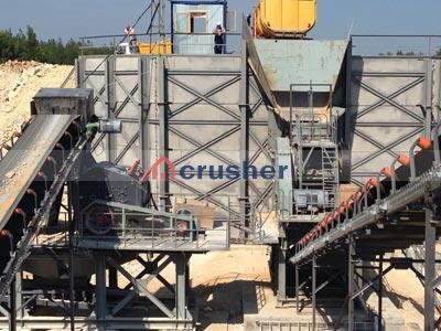
The shaft is divided into two types low and high speed The low speed shaft transfers mechanical energy from the rotor to the gearbox while the high speed shaft transfers mechanical energy from gearbox to generator Yaw is the horizontal moving part of the turbine It turns clockwise or anticlockwise to face the wind The yaw has two main
Get Price